Communication
Protocols
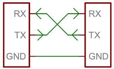
Universal Asynchronous Receiver/Transmitter (UART)
·
Simple,
two-wire protocol for exchanging data and acts as an intermediary between
parallel and serial interfaces
·
Asynchronous: no shared clock
o
The
same bit / baud rate must be the configured in the transmitter and receiver
·
Can
be found as standalone Integrated Circuits (IC) or in microcontrollers – Review
documentation to see if UART is available
Source: Sparkfun Tutorials
|
Parallel Side |
Serial Side |
|
8-bit data bus |
Rx: Receiver |
|
Control pins ·
R/W ·
CLK ·
INT |
Tx: Transmitter |
·
Transmitter appends sync and parity bits to create
a data packet
·
Data packet is sent out the Tx line at the defined baud
rate
·
Data packet is received on the Rx line and sampled at the
defined baud rate
o
Receiving UART picks out the sync bits and delivers the
data
Source: Sparkfun Tutorials
·
Advanced UARTs may place received data into a buffer
o
Buffer: Holding space for data where a microcontroller can
retrieve data from
§ Data
retrieval is first In, first Out (FIFO)
§ Can be
designed to the required size specs
·
Software UARTs can be used if a microcontroller
doesn’t have a UART or needs more
o
Bit-Banging: Technique for digital communication
where software controls GPIO pins to imitate a communication protocol
Serial Peripheral Interface (SPI)
|
Pinout |
Name |
Description |
|
SCLK |
Serial Clock |
Clock
signal from master/controller |
|
SS/CS |
Slave / Chip Select |
Select
signal from master/controller to enable communication with a specific
slave/chip device |
|
MOSI/PICO |
Master Out Slave In / Peripheral In
Controller Out |
Serial
data output from master/controller to slave/peripheral |
|
MISO/POCI |
Master In Slave Out / Peripheral Out
Controller In |
Serial
data output from slave/peripheral to master/controller |
Master/Controller and
Slave/Peripheral are used interchangeably, as are their acronyms
·
Synchronous
serial communication for short-distance wired communication
·
Interface
bus commonly used to send data between microcontrollers and small peripherals
·
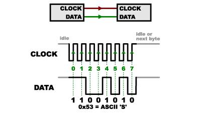
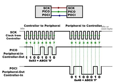
Synchronous:
Data bus uses separate data transmission and clock lines to keep both
sides in sync
o Clock is an oscillating signal that
tells the receiver when to sample bits on a data line
o Data transmits on the rising or falling
edge of the clock signal
§ Data sheet will indicate what edge to
use
§ Once the indicated receiver detects the
edge, data is read from the next bit on the indicated line
o Data transmission speed does not have to
be defined since SPI transmits data on a clock
Source: Sparkfun Tutorials
·
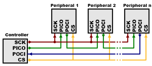
The
controller generates the clock signal and the peripherals follow
o
1
controller and 1 or many peripherals
·
Data
transmits on PICO and POCI lines
o
Controller
uses clock to know in advance when and how much data is transmitted along PICO
vs. POCI
·
Full
Duplex: Separate send and receive lines means that
data can travel along PICO and POCI lines simultaneously
o
The
possibility of this capability can be determined from the peripheral’s data
sheet
Source: Sparkfun Tutorials
·
Chip
Select (CS) is
indicated by the controller and used to select a peripheral for data
transmission
·
A
single controller can interface with one or many peripherals
·
The
CS line is normally held ‘HIGH’ when idle and pulled down when active (Active
Low)
o
Controller
will pull a peripheral’s line ‘LOW’ when data is to be transmitted, then ‘HIGH’
when transmission is complete
o
A
bar over the line label indicates ‘Active Low’ (e.g. ![]() )
)
·
Usually
each peripheral has its own CS line to avoid multiple peripheral signals
transmitting on the same PICO/POCI lines at the same time
o
Binary
Decoder Chips can be
used to multiply CS outputs if peripherals exceed the available CS lines
Source: Sparkfun Tutorials
·
Alternatively,
a single CS can be used for all peripherals when they are daisy-chained so the
output of one peripheral is the input of the next
o
Output-only
use-cases that do not require ‘response’
§
‘Response’
requires loop to close on POCI
·
Data
will have to travel across all peripherals to arrive at the controller
·
Send
enough receive commands to get the data that’s needed
o
Data
overflows from one peripheral to the next, so there must be enough data
transmitted to reach all of them
o
First
piece of transmitted data will reach the all peripherals
Source: Sparkfun Tutorials
Helpful
Links