Motors
Electrical
motors convert electrical energy into mechanical energy, either rotationally or
linearly. Electric current flows through
a conductor in a magnetic field to produce a force that generates motion
(Lorentz Force).
·
The
basic components of a motor include:
o
Stator: Stationary part that produces a
magnetic field using magnets or coils
o
Rotor: Rotating part that is driven by the
stator’s magnetic field
o
Windings: Coils of insulated wire wrapped around
the stator core or rotor to create magnetic fields when electricity flows
through them
o
Shaft: Rod that passes through the motor and
transmits rotational force to a load
o
Power
Source: Supplies
electrical energy to the motor
·
Types
of Electric Motors
o
Direct
Current “DC” Motors: Powered by DC
supply, often found in robotics and electronics
o
Alternating
Current “AC” Motors: Powered by AC
mains, often found in household and industrial applications
o
Stepper
Motors: Rotates in precise steps, used in robotics and CNC
o
Servo
Motors: Rotates with precise position
control, used in automation and robotics
o
Linear
Actuator: Converts rotation to linear motion, used in robotics and standing
desks
Motor
Driving Concepts
·
H-Bridge:
Uses Boolean signals to control the direction that the motor
spins (clockwise vs. counterclockwise)
o
The
Boolean signal defines the motor’s polarity by changing the direction that the
current flows through a motor
o Switching the polarity switches between
a clockwise and counterclockwise motor rotation
|
Clockwise |
Counterclockwise |
|
|
|


·
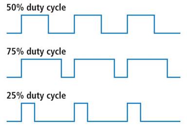
Pulse
Width Modulation (PWM):
Commands a percentage to define how much of a motor’s total available ‘effort’
(Duty Cycle) to output as a digital signal
o
The
power delivered to the motor is not actually reduced to a percentage of the
total motor spec
o
Instead,
the power supplied continually flips between a ‘low’ and ‘high’ state to
simulate a variable voltage that’s bound between the min and max operating
speed
§
This
state flipping is not perceivable to the human eye
·
Motor
Control
o
Motors
can be driven more precisely when a control system is implemented. The selected control system depends on the
motor’s application, but common control systems can include Proportional,
Integral, Derivative (PID) controllers and Bang-Bang (hysteresis)
controllers. These control systems
require a measurement instrument to collect performance feedback that drives
the system controller. A popular
measurement instrument on motors is the tachometer, which measures the motor’s
rotational speed.
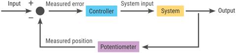
o
These
control systems will generally follow the closed loop detailed below:
·
Desired
motor performance is defined (speed, position, etc.) as a ‘steady-state’ value
·
Initial
signal is sent to the motor as a voltage
·
Motor
rotates given a voltage
·
Measurement
instrument on the motor characterizes the motor’s performance in that moment
·
Measured
value returns to the controller as ‘feedback’
·
Controller
compares the feedback value from the current iteration to the defined
‘steady-state’ value to calculate an error and adjusts the signal sent to the
motor
o
Ideally,
this new signal improves the motor’s performance and reduces the error to
arrive at the desired ‘steady-state’ value
DC Motors
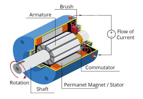
Labeled Brushed DC Motor
Source: powerelectronictips.com
o
DC
Motor-specific Components:
o
Commutator:
Segmented ring that reverses the direction of current in the armature coils and
maintains continuous rotation
o
Armature:
Rotating part of a DC motor (core, windings, commutator)
o
Brushed
vs. Brushless:
o
Brushed
o
Brushless
·
Voltage
à Speed
·
Current
à Torque
·
Gear
Ratio: Motor shaft
turns 48 times for every 1 turn of the output shaft (wheel)
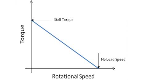
·
Stall
Torque: Maximum
rotational force a motor can produce when the shaft is prevented from turning,
resulting in zero rotational speed
o
When
a motor is at stall torque, it draws maximum current which can lead to
overhearing and damage if stalled for too long
o
Stall
current can be measured by connecting an ammeter in series with the motor,
physically fixing the motor shaft to prevent it from turning, and applying
voltage to the motor. The ammeter
reading when the motor is physically stalled is the stall current.
·
Constant
Voltage: Torque is inversely proportional to Rotational Speed
o
Stall
torque occurs when
rotational speed = 0, so where the torque-speed curve intersects the y-axis
o
Zero-torque occurs when rotational speed = maximum,
also known as the no-load speed
|
|
|
|
|
|
|
|
|
|
|
|
|
|
·
Determine
the motor’s torque and a given speed using the equation of a line to define the
torque-speed curve
|
|
|
|
|
|
|
|
|
|
|
|
Servo Motors
Source: Circuit Geeks
·
Position-controlled
motor that can be useful to precisely control the position of robotics
·
Rotation
range: ![]()
o
No
continuous motor movement
·
Disadvantages:
o
Slower
movements
o
Lower
output power than other motor types
Source: Circuit Geeks
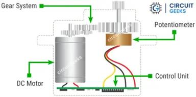
·
Components:
o
DC
Motor
o
Gearbox:
Reduce speed and increase torque; drives position of the output shaft, measured
in degrees
o
Potentiometer:
Monitor the position of the output shaft and deliver position feedback
o
Control
Circuit: Interprets the input signal to determine the position of the arm and
how much movement is required
Source: Circuit Geeks
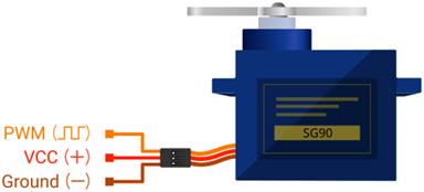
·
Consists
of 3 wires (wire colors may vary by motor):
o
VCC
(5V): Supplies electric current to motor
§
Know
how much power the use-case requires to know how much power / current it will
need to pull from its power source
·
Different
motors and use-cases will have different requirements depending on the size and
workload
§
Power
supply rating should be greater than the stall current of the servo, per servo
connected to the power supply
·
![]()
·
Consider
the PCA9685 for controlling multiple servo motors with one
microcontroller
o
GND
o
Signal
(PWM): Delivers control signal to motor (degrees, ![]() )
)
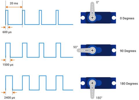
·
Servo
motors are driven by indicating the angle at which the output shaft should be
positioned, expressed in degrees
o
Signal
delivered as PWM
§
Pulse
width determines servo arm position
Source: Circuit Geeks
Helpful
Links