Unmanned
Ground Vehicle (UGV)
This project
was inspired by a curiosity for a very popular technology: Simultaneous
Localization and Mapping (SLAM). From automated
robotic home vacuum systems to show ride vehicles at world-class theme parks,
this technology cleverly intersects mechanics, electronics, and software to
automate a platform’s journey through space.
I’m drawn to this project because it challenges me to approach a design
from the perspective of multiple engineering disciplines and work toward one
technical goal: SLAM.
Tech Stack
|
Mechanical |
Electronics |
Software |
Development
Environment |
|
Fusion 360 |
Raspberry Pi
4 Model B |
Python
3.11.2 |
Visual Studio
(VS) Code |
|
Boss
Laser LS-1630 |
L298N Motor
Driver |
Lightburn |
VS Code
Remote-SSH Extension |
|
Bambu Lab A1
3D Printer |
ESP32
UWB Pro with DW1000 |
Bambu
Studio |
Windows
Subsystem for Linux (WSL) |
|
DC
Motors |
MaUWB STM32 AOA |
|
Linux:
Debian |
|
SG90
Servo Motors |
|
|
GitHub |
Budget
|
Item |
Vendor |
Unit Price |
Qty. |
Units |
TOTAL |
Details |
Notes |
|
Acrylic Sheet 10" H x 8"
W x 0.11" D |
Hobby Lobby |
$3.99 |
4 |
count |
$15.96 |
Platform Panels, Peripheral Mounting
Plates, manufactured with laser cutting |
MFD FX Maker Space |
|
#10-24 x 2-1/2" SS Pan
Philips Machine Screw |
Ace Hardware |
$1.00 |
4 |
count |
$4.00 |
Platform Panel Standoffs |
|
|
#10/24 Nylon Cap (Acorn) Nut |
Ace Hardware |
$1.09 |
4 |
count |
$4.36 |
Platform Panel Standoffs |
|
|
5/16" X 2" Tension Pin
300 Series |
Ace Hardware |
$1.69 |
4 |
count |
$6.76 |
Platform Panel Standoffs |
|
|
Breadboards and Jumpers Kit |
Amazon |
$9.99 |
1 |
count |
$9.99 |
Peripheral Wiring |
|
|
L298N Motor Driver, 2 DC TT
Motors/Wheels |
Amazon |
$7.99 |
1 |
Count |
$7.99 |
Motor and Wheel Assemblies, Motor
Driver Combo Kit |
|
|
3D Print Drive Motor and RasPi Mounts |
OCLS Melrose Ctr. |
$0.05 |
30 |
grams |
$1.50 |
Drive Motors and Raspberry Pi
Mounts |
MFD OCLS Melrose Ctr. |
|
#10-24 x 1/2" Screw |
Ace Hardware |
$0.60 |
8 |
count |
$4.80 |
Fasten RasPi
Block and Motor Mount Blocks to Platform |
|
|
#10-24 Nylon Hex Nut |
Ace Hardware |
$0.45 |
8 |
count |
$3.60 |
Fasten RasPi
Block and Motor Mount Blocks to Platform |
|
|
M3 x 30mm Screw |
Ace Hardware |
$0.60 |
4 |
count |
$2.40 |
Fasten Motor to Motor Mount Block |
|
|
M3 Washer |
Ace Hardware |
$0.55 |
4 |
count |
$2.20 |
M3 Screw to Motor Mount Block
(between screw head and motor mount outer face) |
|
|
M3 Hex Nut |
Ace Hardware |
$0.45 |
8 |
count |
$3.60 |
Fasten Motor to Motor Mount Block
(one on either side of motor, per fastener) |
|
|
#10-24 x 3/8" SS Pan Philips
Machine Screw |
Ace Hardware |
$0.40 |
2 |
count |
$0.80 |
Fasten Caster Mount to Platform |
|
|
#10-24 Nylon Hex Nut |
Ace Hardware |
$0.45 |
2 |
count |
$0.90 |
Fasten Caster Mount to Platform |
|
|
#10-24 x 1/2" Screw |
Ace Hardware |
$0.60 |
2 |
count |
$1.20 |
Fasten L298N Motor Driver Mount to
Platform |
|
|
#10-24 Nylon Hex Nut |
Ace Hardware |
$0.45 |
2 |
count |
$0.90 |
Fasten L298N Motor Driver Mount to
Platform |
|
|
M3 x 10mm Standoff |
Amazon |
4 |
count |
Fasten L298N Motor Driver to Mount |
|||
|
M3 x 6mm Screw |
Amazon |
4 |
count |
Fasten L298N Motor Driver to Mount |
|||
|
M3 Hex Nut |
Amazon |
4 |
count |
Fasten L298N Motor Driver to Mount |
|||
|
Self
Adhesive Caster Wheel |
Amazon |
$0.75 |
1 |
count |
$0.75 |
Purchased in a pack of 8 for $5.99 |
|
|
ESP32 UWB Pro with Display with
DW1000 |
Makerfabs |
$54.80 |
2 |
count |
$109.60 |
Localization module – need 4
modules total for trilateration (1 tag, 3 anchors) |
|
|
3D Print SG90 Servo Motor Mount |
OCLS Melrose Ctr. |
$0.05 |
2 |
grams |
$0.10 |
SG90 Servo Motor Mount |
MFD OCLS Melrose Ctr. |
|
#10-24 x 3/8" SS Pan Philips
Machine Screw |
Ace Hardware |
$0.40 |
2 |
count |
$0.80 |
Fasten SG90 Servo Motor Mount to
Platform |
|
|
#10-24 Nylon Hex Nut |
Ace Hardware |
$0.45 |
2 |
count |
$0.90 |
Fasten SG90 Servo Motor Mount to
Platform |
|
|
M2 x 5 + 3mm Standoff |
Amazon |
|
2 |
count |
|
Fasten SG90 Servo Motor to Mount |
|
|
M2 x 3mm Screw |
Amazon |
|
2 |
count |
|
Fasten SG90 Servo Motor to Mount |
|
|
M2 Hex Nut |
Amazon |
|
2 |
count |
|
Fasten SG90 Servo Motor to Mount |
|
|
#10-24 x 3/8" SS Pan Philips
Machine Screw |
Ace Hardware |
$0.40 |
2 |
count |
$0.80 |
Fasten Breadboard Mount to
Platform |
|
|
#10-24 Nylon Hex Nut |
Ace Hardware |
$0.45 |
2 |
count |
$0.90 |
Fasten Breadboard Mount to
Platform |
|
|
3D Print 6V Battery Mount |
OCLS Melrose Ctr. |
$0.05 |
19 |
grams |
$0.95 |
6V Battery Mount |
MFD OCLS Melrose Ctr. |
|
#10-24 x 3/8" SS Pan Philips
Machine Screw |
Ace Hardware |
$0.40 |
2 |
count |
$0.80 |
Fasten Battery Mount to Platform |
|
|
#10-24 Nylon Hex Nut |
Ace Hardware |
$0.45 |
2 |
count |
$0.90 |
Fasten Battery Mount to Platform |
|
|
2/4/6/8 x 1.5V AA Battery Holder |
Amazon |
$8.90 |
1 |
count |
$8.90 |
|
|
|
Crimp Pin Connector Kit (Pins,
Housings) |
Amazon |
$9.99 |
1 |
count |
$9.99 |
Miscellaneous wire work |
|
|
Polyolefin Heat Shrink Tube 1/8”
(3.2mm) |
Ace Hardware |
$3.59 |
1 |
count |
$3.59 |
Pack of 7; Miscellaneous wire work |
|
|
M2.5 x 10 + 6mm Standoff |
Amazon |
|
4 |
count |
|
Per module – 4 Modules in
Assembly: 1 Tag, 3 Anchors |
|
|
M2.5 x 15 + 6mm Standoff |
Amazon |
|
4 |
count |
|
Per module – 4 Modules in
Assembly: 1 Tag, 3 Anchors |
|
|
M2.5 x 6mm Screw |
Amazon |
|
8 |
count |
|
Per module – 4 Modules in
Assembly: 1 Tag, 3 Anchors |
|
|
M2.5 Hex Nut |
Amazon |
|
8 |
count |
|
Per module – 4 Modules in
Assembly: 1 Tag, 3 Anchors |
Technical
Drawings
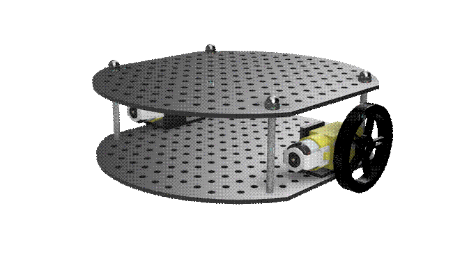
Mobile Platform Base
|
|
|


·
The
platform bases are designed like a pegboard to make the UGV more modular, and
they’re manufactured from acrylic using a laser cutter
o
This
design facilitates designing and fastening peripheral mounts/attachments and
flexibly position them as needed
o
The
platform bases are manufactured from acrylic for the material’s low
conductivity and ability to withstand heat, thereby reducing unintended
influence on electronic components
o
Laser
cutting the design onto an acrylic sheet allowed for consistent and accurate
cuts
·
Laser Cut at Maker FX Maker Space on Boss Laser
LS-1630
Raspberry Pi 4 Model B Mounting Block
|
|
|


·
3D
Printed at Orange County Library – Melrose Center Maker Space on Bambu Lab A1
printer
Breadboard Mounting Plate
|
|
|


·
Breadboard
dimensions: 3.25” X 2.125”
·
Breadboard
comes with adhesive sheet to adhere to mounting plate
·
Laser Cut at Maker FX Maker Space on Boss Laser
LS-1630
6V Battery Mounting Block
|
|
|


·
Rev
A:
o
Fastener
head clearance too tight
o
It
is difficult to remove battery box from mounting block without flipping upside
down
§
Needs
space to fully grip battery box for removal from mounting block
·
3D
Printed at Orange County Library – Melrose Center Maker Space on Bambu Lab A1
printer
DC ‘TT’ Motor
|
|
|


·
DC ‘TT’
Motor assembly file from GrabCAD, as indicated in
drawing notes
·
Technical
drawing by me
DC ‘TT’ Motor Mounting Block
|
|
|


·
Only
the right drive motor mount was modeled, so the model was mirrored in the Bambu
Studio slicing software when 3D printed to produce the left drive motor mount
·
3D
Printed at Orange County Library – Melrose Center Maker Space on Bambu Lab A1
printer
L298N Mounting Plate
|
|
|


·
Laser Cut at Maker FX Maker Space on Boss Laser
LS-1630
SG90 Servo Motor Mounting Block
|
|
|
|
|
|
|
|
|


·
Rev
A
o
The
mounting block is designed to fasten to the servo motor via two M2.5x5+6mm
standoffs, so the print will be 5mm too short for a motor to sit directly in
the saddle without standoffs
o
3D
Printed at Orange County Library – Melrose Center Maker Space on Bambu Lab A1
printer
·
Rev
B
o
Added
missing width dimension in drawing
o
Taller
standoff supports clearing fastener heads and motor wires’ bend radius
o
Narrower
standoff supports improving servo fit in mount saddle
o
Standoff
support thread holes’ diameter increased from 2.1mm to 2.2mm
o
Use
M2x5+3mm standoffs to fasten servo motor to mount
o
3D
Printed at Orange County Library – Melrose Center Maker Space on Bambu Lab A1
printer
·
Rev
C
o
Corrected
over-toleranced dimensions from Rev B
o
New
design allows SG90 servo motor to sit in the mount saddle slot
o
SG90
servo motor fastens to the mount with M2 screws and nuts
o
Replaced
fastener holes with thru holes to allow M2 fasteners to clear the holes and
fasten with the nut
o
Internal
edges rounded to reduce stress points when bearing load
o
3D
Printed on Bambu P1S printer
ESP32 UWB DW1000 Housing
|
|
|


·
Made of clear acrylic so that pin labels and
LCD (if present) are visible
·
2 housing plates per module:
o
Top (side with LCD, if present)
§ M2.5 x 10mm
standoffs
o
Bottom (side with pinout labels), OPTIONAL
§ M2.5 x 15mm
standoffs
·
Laser Cut at Maker FX Maker Space on Boss Laser
LS-1630
Pictures of Manufactured and Assembled
UGV
|
|
|
|
|
|


Mechanical
·
More
technical information about motors can be found in my Motors
Tech Notebook.
·
Code
for driving motors with Python on the Raspberry Pi can be found in my github:
o Raspberry
Pi Motor Hat Driver
DC Gear Box Motor – DC ‘TT’ Motor
Technical Specifications
|
DC Voltage |
3V |
4.5V |
6V |
|
Current |
150mA |
155mA |
160mA |
|
Gear Ratio |
1:48 |
1:48 |
1:48 |
|
Minimum Operating Speed |
90RPM +/- 10% |
- |
200RPM +/- 10% |
|
Stall Torque |
0.4kg-cm |
- |
0.8kg.cm |
SG90 Micro Servo Motor
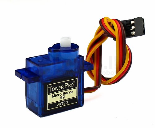
Technical Specifications
|
DC Voltage |
4.8V |
6V |
|
Current |
155mA |
160mA |
|
Approximate Operating Speed |
0.09 - 0.15 seconds per 60 degrees |
0.09 - 0.15 seconds per 60 degrees |
|
Stall Torque |
1.3kg.cm |
1.5kg.cm |
|
Operating Angle |
180 |
180 |
Electrical /
Electronics
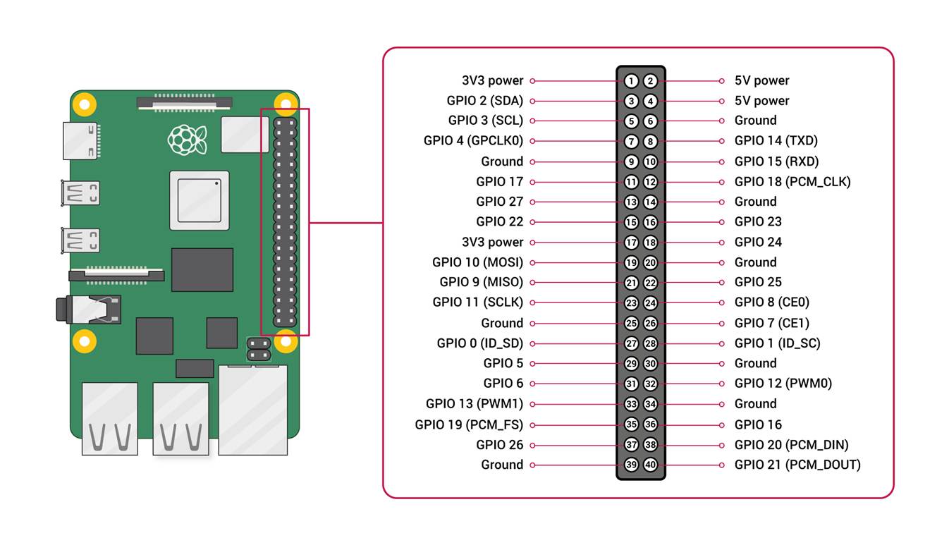
Raspberry Pi 4 Model B
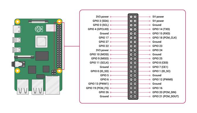
|
Pin Number |
Pin Description |
Pin Assignment |
Pin Number |
Pin Description |
Pin Assignment |
|
1 |
3V3 POWER |
2 |
5V POWER |
L298N POWER IN 5V |
|
|
3 |
GPIO 2 (SDA) |
4 |
5V POWER |
Object Detection Servo 5V |
|
|
5 |
GPIO 3 (SCL) |
6 |
GND |
L298N GND |
|
|
7 |
GPIO 4 (GPCLK0) |
8 |
GPIO 14 (TXD) |
ESP32 UWB DW1000 RXD |
|
|
9 |
GND |
10 |
GPIO 15 (RXD) |
ESP32 UWB DW1000 TXD |
|
|
11 |
GPIO 17 |
L298N MOTOR B IN1 (RIGHT) |
12 |
GPIO 18 (PCM_CLK) |
|
|
13 |
GPIO 27 |
L298N MOTOR B IN2 (RIGHT) |
14 |
GND |
|
|
15 |
GPIO 22 |
L298N MOTOR B EN (RIGHT) |
16 |
GPIO 23 |
L298N MOTOR A IN1 (LEFT) |
|
17 |
3V3 POWER |
ESP32 UWB DW1000 |
18 |
GPIO 24 |
L298N MOTOR A IN2 (LEFT) |
|
19 |
GPIO 10 (MOSI) |
|
20 |
GND |
ESP32 UWB DW1000 |
|
21 |
GPIO 9 (MISO) |
|
22 |
GPIO 25 |
L298N MOTOR A EN (LEFT) |
|
23 |
GPIO 11 (SCLK) |
|
24 |
GPIO 8 (CE0) |
|
|
25 |
GND |
26 |
GPIO 7 (CE1) |
||
|
27 |
GPIO 0 (ID_SD) |
28 |
GPIO 1 (ID_SC) |
||
|
29 |
GPIO 5 |
30 |
GND |
||
|
31 |
GPIO 6 |
32 |
GPIO 12 (PWM0) |
Object Detection Servo Signal |
|
|
33 |
GPIO 13 (PWM1) |
34 |
GND |
Object Detection Servo GND |
|
|
35 |
GPIO 19 (PCM_FS) |
36 |
GPIO 16 |
||
|
37 |
GPIO 26 |
38 |
GPIO 20 (PCM_DIN) |
||
|
39 |
GND |
40 |
GPIO 21 (PCM_DOUT) |
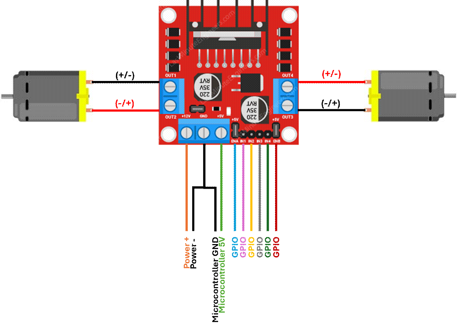
L298N Motor Driver
·
The
DC motors are rated for a voltage that exceeds what a microcontroller outputs
·
A
motor driver provides the motors with an external power source that meets the
motor’s specifications but receives logic signals from the connected
microcontroller
·
The
L298N microcontroller has H-bridge and Pulse Width Modulation (PWM) capability,
controlling the motor’s output effort (i.e. rotation speed) and direction
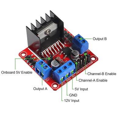
|
Pin
Label |
Pin
Description |
Pin
Notes |
|
Output
A |
DC
Motor A |
DC
Motor Leads |
|
Output B |
DC Motor B |
DC
Motor Leads |
|
12V Input |
Motor Power Source (+) up to 12V input |
|
|
GND |
Motor Power Source (-) / Microcontroller
Ground |
|
|
5V Input |
5V from Microcontroller Pin for Driver
Logic |
|
|
Channel-A Enable |
PWM: DC Motor A |
1
pin on channel for duty cycle % (float between 0 and 1) |
|
Channel-A IN1/IN2 |
H-Bridge: DC Motor A |
2
pins on channel for Boolean signals (CW: T/F, CCW: F/T) |
|
Channel-B Enable |
PWM: DC Motor B |
1
pin on channel for duty cycle % (float between 0 and 1) |
|
Channel-B IN1/IN2 |
H-Bridge: DC Motor B |
2
pins on channel for Boolean signals (CW: T/F, CCW: F/T) |
·
The
diagram below shows how the L298N motor driver is connected to the DC motors
and the microcontroller logic pins
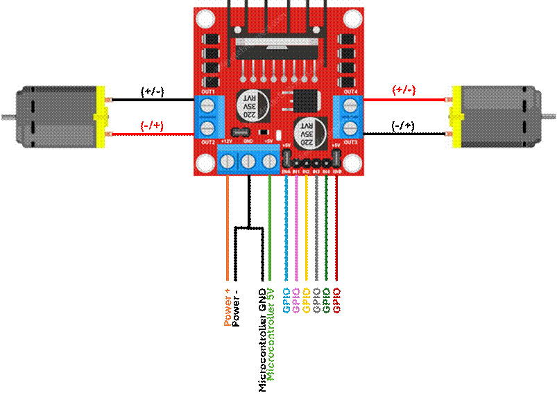
·
Code
for driving motors on the L298N motor driver with Python on the Raspberry Pi
can be found in my github:
Ultra Wideband (UWB)
·
Ultra-Wideband
(UWB) is a high-precision, short-range wireless radio technology used for
accurate, low-power device localization at short distances
o
Devices
send multiple short radio pulses over a wide frequency band and measure the
time it takes for signals to travel between one another (Time of Flight, ToF) to determine their distance and position
o
Large
bandwidth provides high data rates and stability to reduce interference while
enabling precise positioning
§
Ideal
for indoor positioning and navigation
|
Peripheral |
Proposed Purpose |
|
ESP32 UWB Pro DW1000 |
Localization |
|
MaUWB STM32 AOA |
Docking |
·
These
modules can communicate with the microcontroller using Universal Asynchronous
Receiver/Transmitter (UART) protocol, an asynchronous serial communication for
short-distance wired communication
o See
Communication Protocols: UART in Tech Notebook
ESP32 UWB Pro with DW1000
|
CPU |
ESP32 - WROVER |
|
UWB |
DW1000 |
|
Measuring Distance |
200M |
|
UWB Channel |
2/5 |
|
Board USB Supply Voltage Range |
4.8~5.5V, 5.0V Typical |
|
Other Features |
WiFi, BlueTooth |
The ESP32
documentation defines the pinout for the chip that’s soldered on Makerfab’s board.
The board pins map to the ESP32 chip pins with the corresponding name,
as defined in the documentation.
|
ESP32-WROVER Pin Layout Makerfabs ESP32 UWB with DW1000 Documentation |
ESP32-WROVER Pin Definitions Makerfabs ESP32 UWB with DW1000 Documentation |
ESP32 UWB Pro Makerfabs
Board Makerfabs ESP32 UWB Pro with Display |
|
|
|
|


·
UWB
DW100 Module Calibration:
Distance readings between tag and anchor modules require proper calibration to
achieve accurate measurements.
o
Each
module has an antenna delay value that accounts for signal propagation through
the PCB trace and antenna
§
If
the antenna delay is wrong, the distance measurements will consistently be off
by a fixed amount
o
Antenna
Delay is the value that
must be tuned for distance measurement calibration
o
The
procedure below details how I calibrated the UWB
modules:
§
Place
the tag and anchor modules exactly 1m from each other
§
Confirm
the following:
·
Baud
rate is the same for the anchor and tag
·
Antenna
delay is the same for the anchor and tag
§
Record
the antenna delay value for 4-6 iterations:
·
Collect
distance readings for at least 50 cycles from the anchor module using the
Arduino Open Serial Monitor
o
Confirm
that the baud rate in the serial monitor matches the baud rate oof the anchor
and tag
·
Calculate
the average distance reading from the anchor module data
·
Knowing
that the anchor and tag are placed 1m from each other, calculate the error in
the distance measurement and the known distance between modules
|
|
·
Higher
antenna delay means that more of the round-trip time was internal delay instead
of free-space travel, so some time is subtracted from the ToF
calculation
Antenna Delay Tuning Intuition
|
If… |
Then… |
|
|
Increase
antenna delay |
|
|
Decrease
antenna delay |
·
Each
unit of antenna delay corresponds to approximately 1 DW1000 clock tick, which
equals 4.7mm of distance
·
Divide
the error by the distance per unit antenna delay to calculate
the adjustment
|
|
·
Add
the adjustment to the current antenna delay to calculate
the new antenna delay value
|
|
·
Use
this new antenna delay value in the next iteration
·
Update
the antenna delay value in the anchor and tag code before starting the next
iteration
o
Below
is the data I collected from mathematically tuning the UWB modules, tabulated
and plotted:
|
Distance Measurement Average |
Current Antenna Delay |
Error |
Antenna Delay Adjustment |
New Antenna Delay |
|
1.880839 |
16384 |
0.880839 |
187 |
16571 |
|
0.142353 |
16571 |
-0.85765 |
-182 |
16389 |
|
2.051922 |
16389 |
1.051922 |
224 |
16613 |
|
-0.13342 |
16613 |
-1.13342 |
-241 |
16372 |
|
2.087273 |
16372 |
1.087273 |
231 |
16603 |
|
|

§
The
data indicates a linear relationship between the antenna delay value and the
measurement error
§
I
used the data from the experiment above to perform a linear regression and
define the equation of a trendline. Once
defined, I calculated the antenna delay that should yield 0 error and
repeated the error and adjustment calculations.
§
Using
the tuning intuition defined above, I manually nudged the antenna delay value
until the measurement error was sufficiently minimized.
o
Below
is the data I collected from manually tuning the UWB modules, tabulated and
plotted:
|
Distance Measurement Average |
Current Antenna Delay |
Error |
Antenna Delay Adjustment |
New Antenna Delay |
|
1.096311 |
16488 |
0.096311 |
20 |
16508 |
|
1.060593 |
16485 |
0.060593 |
13 |
16498 |
|
0.992762 |
16482 |
-0.00724 |
-2 |
16480 |
|
|

·
UWB
DW1000 Module Data Acquisition via UART:
o
I
wrote some code that collected data from the UWB tag over UART but noticed that
the data acquisition rate would lag over time
o
I confirmed
that data was not being stored in a data structure that was growing
indefinitely
o
The
problem persisted, so I investigated further and noticed that data from prior
transactions had accumulated in the buffer
o
Buffer: A temporary storage area in memory that
holds data while it’s being transferred between two entities operating at
different speeds and/or schedules
o
Since
UART uses a FIFO buffer to store incoming bytes, the most recent data is queued
behind data from previous cycles
§
UART
buffers hold incoming bytes from the peripheral until software is ready to read
them.
·
Peripheral
sends the data on its own clock
·
Acquisition
device reads data when it’s ready
·
Buffer
bridges the gap between the peripheral and data acquisition device
o
The
buffer had to be cleared before each acquisition cycle so that the most recent
data wouldn’t lag behind residual data from previous
cycles
§
This
ensures that the acquisition captures a current peripheral output
·
UWB
DW1000 Module Data Filtering:
o It’s common for data from a peripheral
to be noisy
o There are various reasons why a signal
would be noisy, including but limited to:
§ Electromagnetic Interference (EMI): Nearby motors, power lines, switching circuits
induces voltages onto signal lines
§ Cable Length: Longer cables can pick up interference,
causing signal degradation
§ Voltage Ripples: Unclean power supply introduces
fluctuations that ride on top of the signal
§ Clock Jitter: Variations in the clock signal cause
sampling to occur at misaligned moments
§ Cross-Talk: Adjacent signal lines on PCB couple into each other
§ Vibrations: Intermittent contact between connectors
or stress on cables
o Since the peripheral data can be noisy
for various reasons, but accurate localization requires reliable distance
measurements between tags and anchors, I implemented a low-pass filter
that reduces high-frequency signals above a threshold called the cutoff
frequency.
Raw Data Acquisition vs. Data Filter
Implementation
|
|

Algorithms
·
All
algorithms implemented in this UGV are documented in my Portfolio!
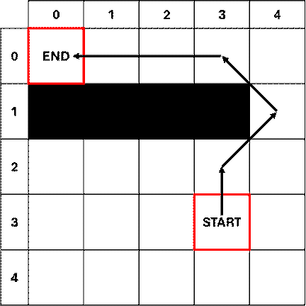
o Localization Algorithm Write-Up: Trilateration
§ This UGV uses a trilateration algorithm
to locate itself in a known environment
§ Ultra-Wide Band (UWB) modules are
mounted in the system to measure the distances needed for the trilateration
algorithm
·
3 anchor
modules are stationary in the local frame (i.e. the environment) that the UGV
is navigating (denoted by the ★ below)
·
1 tag
module is mounted on the UGV that navigates the environment
|
|

§
Anchor
modules’ known location coordinates in the local frame are centers of the range
circles
§
The
measured Euclidean distance between the UGV tag module and each fixed anchor
module are the range circles’ radii
§
The
intersection point of all 3 range circles is the UGV’s location coordinate in
the local frame
o Path Planning Algorithm Write-Up: A*
Path Planning
§ This UGV uses information about its
environment’s layout to plan its path trajectory using the A* path planning
algorithm
§ The A* path planning algorithm
mathematically determines the most efficient trajectory between two points,
avoiding known obstacles like walls and stationary objects
Software
·
All
code implemented in this UGV is publicly available on my github!
o
Localization:
Trilateration Algorithm
o
Path
Planning: A* Path Planning Algorithm
o Raspberry
Pi Motor Hat Driver
Helpful
Links
·
Makerfabs ESP32 UWB with DW1000
·
Makerfavs ESP32 UWB & Display source code - github
·
Getting Started with ESP32 UWB Board - techiesms