VendArt
at MakerFX

This effort aims to restore a National
Vendors, Inc. Manual Cigarette Merchandiser Series 222, which was a classic mechanical
cigarette vending machine that was popular between the 1960s and 1980s. The machine that I’m helping restore is from
1975, as indicated by a stamp on the vending machine’s internal hardware.

Date stamp found inside the merchandiser
Another MakerFX member owns this
project, but I’m supporting the effort by restoring the mechanical vending
mechanisms and integrating modern payment solutions while preserving the
machine’s original and existing hardware.
When completed, this vending machine will sell local makers’ unique
makes at various Central Florida maker events, like Maker Faire Orlando.
The machine’s vending mechanisms are
locked when idle, preventing the pull knobs from dispensing items from their
respective magazines. When payment is
accepted, a solenoid engages the vending mechanisms to unlock the pull knobs
and enable vending. I was tasked with
replacing the missing solenoid, designing and implementing a solenoid driver,
and writing the code that drives the solenoid during a transaction.
Tech Stack
|
Mechanical |
Electronics |
Software |
Development
Environment |
|
Fusion 360 |
Raspberry Pi Pico W
(Development) |
Python
3.13.9 |
Visual Studio (VS)
Code |
|
Bambu Lab P1S 3D
Printer |
Raspberry Pi Zero
2W (Production) |
Bambu
Studio |
VS Code Extension:
SSH FS |
|
Solenoid
12V 10mm 5N Push Pull |
MP1584EN
DC-DC Buck Converter |
Square
API Developer |
PuTTY |
|
Infrared
Thermometer |
IRLZ44NPBF
Logic Level MOSFET |
Webhooks |
Thonny |
|
Prototyping |
Breadboard,
Perfboard |
ngrok
(Secure Tunnels) |
GitHub |
|
Testbed
and Experiment Design |
Soldering |
|
|
Mechanical
|
|
|
|
|


Left to Right: Internal vending unit front,
merchandise magazines, internal vending unit side, vending lock mechanism
detail
Solenoid 12V 10mm 5A Push Pull
|
|
|


Technical Specifications
|
Voltage |
12VDC |
|
Current |
1.7A |
|
Force |
5N |
|
Stroke |
10mm |
XYZ Adjustable Solenoid Carriage (left)
and Mount (right)
|
|
|


XYZ Adjustable Solenoid Carriage and
Mount Assembly
|
|

·
Carriage
and mount were designed in Fusion 360
·
Carriage
and mount were 3D printed with PLA on the Bambu P1S
|
|
|
|


Detail of solenoid on XYZ carriage and
mount, and fastened to existing machine bracket
Retrofitted XYZ Adjustable Solenoid
Carriage and Mount Assembly on Existing Bracket
|
|
|
|


·
The
solenoid carriage and mount are adjustable in the XYZ directions, so the
solenoid can be precisely positioned to engage the vending lock mechanism
o
The
solenoid fastens to the carriage
o
The
carriage fastens to the mount
o
The
mount fastens to the vending machine’s existing bracket
· I designed this XYZ solenoid carriage
and mount assembly to fit the existing bracket
· This design makes it possible to position
the solenoid plunger (piece that extends and retracts) with the vending
machine’s mechanical lock mechanism
· The XYZ carriage and mount positions are
‘locked’ with screws, washers, and nuts creating bolted joints
|
|

Bolted Joint
Electronics Mounting Block: Parts
|
|
|
|


Left to Right: Electronics Plate,
Cantilevered Snap Locking Block, Manufactured and Assembled Sub-Assembly
·
Electronics
plate and cantilevered snap locking block were designed in Fusion 360
·
Electronics
plate and cantilevered snap locking block were 3D printed with PLA on the Bambu
P1S
·
The
electronics mounting block is a 2-part subassembly that mounts the Raspberry Pi
and solenoid driver to the vending machine
·
The
electronics plate slots into the locking block, and the swinging cantilever
snap secures the plate in the locking block
·
This
mounting subassembly was designed to facilitate removal from the vending
machine when the inner mechanics are placed back in the housing
o
The
clearance between the inner mechanics and the housing is very tight, so tools
cannot easily be used to remove electronics fasteners for maintenance
o
Using
a locking slide mechanism design makes it easier to retrieve electronics from
the front of the vending machine without removing fasteners
|
|
|
|


Electronics plate slotting into the
cantilevered snap locking block
|
|

Electronics Mounting Block installed in
the vending machine
Solenoid Intermittent Duty Cycle
Temperature Testing
· The solenoid’s plunger extends by
creating a magnetic field when current flows through the tightly wound coils
surrounding the plunger
· Continuous current flowing through the
solenoid coils produces a lot of thermal energy (heat)
o I reduced the solenoid’s input voltage
from the rated 12V to 6V to reduce the heat produced when current is flowing
through the coils
· Since the solenoid is mounted to a
carriage and mount that was 3D printed with PLA, I need to confirm that the
heat produced by the solenoid does not exceed the melting point of PLA
·
I
created a test bed to measure the temperature of the solenoid with an infrared
thermometer
o
I
attempted to keep the ambient temperature constant throughout each experiment
run
§
No
AC running, ambient temperature measured during the experiment
o
The
infrared thermometer was mounted onto a tripod to secure its distance from the
solenoid through the experiment
§
The
infrared thermometer’s documentation recommends measuring a temperature from
14”, so I mounted the thermometer at 14” from the solenoid’s top surface where
the temperature was measured
o
The
solenoid was attached to the carriage mount to observe the solenoid’s
temperature effect on the PLA
o
The
carriage mount was securely taped to the test bed to reduce movement between
engages and disengages
·
I
wrote code to iterate through an engage and disengage procedure that parallels
the use-case
o
This
makes the experiment repeatable and the data more accurate
o
Code
available on github
|
|
|


Solenoid Duty Cycle Testbed Setup
o
Manually
pressing the trigger shakes the mounted infrared thermometer, which then shakes
the laser and moves the point where the temperature is measured between
readings
o
I
eliminate the movement produced from physically pressing the thermometer
trigger by clamping down the trigger, which puts the thermometer in an ‘always
scanning’ mode
o
Eliminating
human interaction with the testbed drastically reduces the risk of human error
skewing the data
o
The
thermometer can now consistently measure the temperature at precisely the same
location on the solenoid between cycles
|
|
|


Clamped Trigger on Infrared Thermometer
·
Goal
o Confirm that the solenoid operates as
intended without compromising the integrity of the mechanical system
o Confirm that the heat produced on the
solenoid’s outer surfaces by coils does not exceed the melting temperature of
the PLA carriage and mount
· Procedure
o
Measure
surface temperature at the designated location BEFORE starting engage-disengage
cycles
§
This
location is where the cycle temperatures will be measured for the entire
experiment
o
For
130 duty cycles:
§
Solenoid
engages for 15 seconds
§
Solenoid
disengages and temperature is measured at the designated location
§
Solenoid
remains disengaged for 10 seconds
o
This
experiment iterated through an engage-disengage cycle for multiple duty cycles,
and was repeated at various locations on the solenoid
o
NOTE: DO NOT touch the solenoid or move the
infrared thermometer during the experiment
o
NOTE: Wait until the solenoid returns to
ambient temperature before proceeding to the next experiment solenoid location
Locations on solenoid where temperatures
were measured
|
|
Center
Side |
|
|
Center V
Leads Side |
|
|
Center |
|
|
Center
Plunger End |
|
|
Center
Spring End |
· Results
o
Duty
Cycles 1-100: Capture the temperature rise toward a temperature steady-state
o
Duty
Cycles 101-130: Measure steady temperature
|
|
|


Left: Solenoid Cycle Temperature Rise
and Steady-State Data
Right: Solenoid Steady-State Temperature
Data
o Data Variability
§ Variance calculates the average of the squared
distance from the mean, which measures the distribution of the data
· Low variance is an indication of consistent
measurements during data acquisition and high repeatability. Conversely, high variance indicates unusual
or inconsistent data
§
Standard
Deviation measures the
spread of a set of values around the average, where a low standard deviation
indicates more values close to the average
§ Coefficient of Variability measures how far the standard deviation
is from the data average
·
This
value is used to determine a ‘low’ standard deviation, ideally within 10%
§
Variability
in the data can be attributed to various factors, including but not limited to:
·
Human
error
·
Environmental
influences (temperature, humidity, sunlight, etc.)
·
Measurement
device specifications, tolerances, error, etc.
·
Test
procedures
·
Unexpected
test anomalies (i.e. things that may happen during the experiment that are not
directly related to the experiment)
§
The
equations below are used to calculate the sample variance and standard
deviation in the steady-state data acquisition
·
Sample
variance subtracts 1 from the number of data points in the denominator (Bessel
correction), which accounts for potential biases in the data
acquisition. This increases the variance calculation as a ‘worst case’
|
Data
Average |
|
|
Sample
Variance |
|
|
Standard
Deviation |
|
|
Coefficient
of Variability |
|
|
Location on Solenoid |
Measured Ambient Temperature |
Solenoid Steady-State Data Average
Temperature |
Solenoid
Steady-State Data Standard Deviation |
Solenoid
Steady-State Data Coefficient of Variability |
|
Center Side |
|
|
|
|
|
Center V Leads Side |
|
|
|
|
|
Center |
|
|
|
|
|
Center Plunger End |
|
|
|
|
|
Center Spring End |
|
|
|
|
o
This
data shows low variance, which means that the data collected was relatively
close to the average
o
Since
the data has low variance, I can reliably use the steady-state data average
temperatures to assess the active solenoid’s performance and effects on the
mechanical system
§
This
low variance metric can indicate that:
·
The
thermometer was consistent with its measurements
·
Test
procedures were consistent between iterations
Heat map of the solenoid steady-state
temperature data measured under duty cycle load
o
The
solenoid appears to have entered a steady-state temperature after about 80
engage-disengage duty cycles
o
Interestingly,
the hottest point on the solenoid was at its steady-state during the
engage-disengage duty cycling experiment was near the ![]() leads
leads
o
The
coolest point on the solenoid at its steady-state during the engage-disengage
cycling experiment was at the at the solenoid’s side opposite the ![]() leads
leads
§
This
side of the solenoid is open, so the heat from the coils can dissipate more
easily compared to points along the coil that are enclosed by the metal housing
· Conclusion
o The average solenoid steady-state
temperature when cycling had a range of ![]()
o PLA begins to soften at ![]() and melts at
and melts at ![]()
o This cycle test was more aggressive than
the cycles that the fielded solenoid will undergo and was still ![]() under the PLA softening temperature
under the PLA softening temperature
o Given the experiment results, the heat
produced from the active solenoid should not affect the
PLA carriage mount
o As an extra experiment, I allowed the
solenoid to cycle through engage and disengage for 200 cycles with no impact to
the solenoid’s performance or the PLA carriage mount
§ No data collected – Just observation for
any impacts to the system at high cycle counts
· How to Improve Future Experiment
o Automate temperature readings with
software instead of manually pressing the thermometer trigger
§ Reduces human error by with more
consistent timing between measurements
§
Collect
more frequent temperature data throughout the experiment to create a more
complete temperature profile of the solenoid
o
Perform
experiment in a more controlled environment
§
Thermal
chamber to control the ambient temperature and reduce external influences (AC,
sunlight, etc.)
§
Controlling
ambient parameters would also normalize the data, ensuring that the temperature
rise is comparable among all iterations
·
The
data is reliable for my use-case, but a controlled environment could
parameterize the solenoid more precisely
Electronics
Raspberry Pi Pico W, Dev
|
|
|


Raspberry Pi Zero 2W, Prod
|
|
|


MP1584EN DC-DC Buck Converter (Step-Down
Converter)
|
|
|
|


·
I
wanted the solenoid and microcontroller to share one 12VDC power source, but
both components have different electrical requirements:
o
Solenoid:
12VDC, 1.7A
o
Raspberry
Pi Pico W: 5V, 95mA
·
A
buck converter, AKA step-down converter, efficiently reduces a higher input DC
voltage to a lower output DC voltage
o
This
protects the lower-voltage components that are connected to a higher DC source
voltage
·
An
inductor stores and releases electromagnetic field and smooths the current by
resisting rapid changes
·
A
switch creates a duty cycle that outputs a desired voltage lower than the
source
o
The
lower the duty cycle, the lower the store in the inductor
o
Think
Pulse Width Modulation (PWM)
o
The
switch is usually a transistor (MOSFET)
·
A
diode creates a path for the current when the switch is turned off
·
A
capacitor smooths the voltage rippled
·
The
buck converter unit uses a control (potentiometer) to control the output
voltage
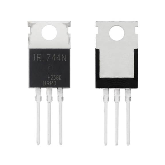
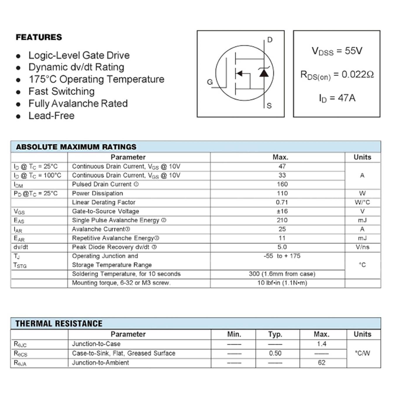
IRLZ44NPBF Logic Level MOSFET

IRLZ44N
Logic-Level MOSFET
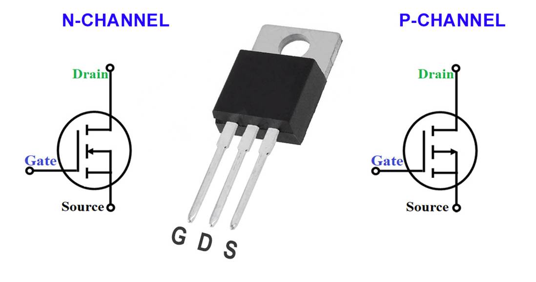
·
A
MOSFET is an electronic switch that controls current flowing through a
semiconductor channel using an electric field
o
MOSFET
Terminals
§
Gate
(G): Control Input
§
Drain
(D): Where current flows out
§
Source
(S): Where current flows in

o
N-Channel:
§
Turns
on when the gate is more positive than the source
§
Current
flows from drain to source
§
Efficient
and low heat
§
Motor
drivers, solenoids, power supplies, high-current applications
o
P-Channel
§
Turns
on when the gate is more negative than the source
§
Current
flows from source to drain
§
Simpler
but less efficient at high currents (higher ![]() )
)
§
Battery-powered
devices
·
The
IRLZ44N is a logic-level N-channel MOSFET, which allows us to engage and
disengage the solenoid by passing a boolean to the MOSFET gate with the
solenoid driver code
·
2
main parameters for selecting the appropriate MOSFET: Voltage (V) and Current
(I)
|
|
|
|
· MOSFET Spec Sheet
o
Spec
sheet assumes proper cooling, so operating the MOSFET at the rated specs
without proper cooling (fans, heat sinks, etc.) can overheat or melt the unit
o
The
Current spec only says that the MOSFET will not melt when operating at 47A when
properly cooled
§
While
the Current and Voltage are used to determine how a system will operate, the
MOSFET’s internal resistance, ![]() , sets the threshold
, sets the threshold
·
![]() tells how much power needs to dissipate from
the MOSFET at a constant load
tells how much power needs to dissipate from
the MOSFET at a constant load
o
Constant
Load: >10 seconds without a heat sink
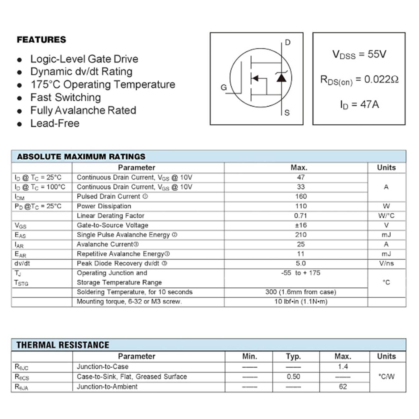
IRLZ44N
MOSFET Spec Sheet
· Thermal Power Generated
o
Recall
– the internal resistance, ![]() , is the spec that we will use to
threshold our MOSFET selection calculations
, is the spec that we will use to
threshold our MOSFET selection calculations
o
Since
there isn’t perfect control of the load on the MOSFET, we degrade the ![]() by 20-30%
by 20-30%
§
Increase
![]() by 20%:
by 20%:
![]()
|
|
o
Now
calculate the thermal power generated, ![]() , by the system given the load’s specs
, by the system given the load’s specs
§
Since
we are using the MOSFET to drive the solenoid, we are using the solenoid specs
defined above as the load
|
|
|
|
|
|
· Thermal Power Lost
o
These
thermal losses need to somehow escape the MOSFET, and that can be determined
with the thermal resistance, ![]()
§
This
tells you how much the MOSFET will heat up for each watt of thermal loss, ![]()
o
Now
that we’ve solved for ![]() , we can calculate the thermal losses to
confirm that they are within the MOSFET’s specifications
, we can calculate the thermal losses to
confirm that they are within the MOSFET’s specifications
§
The
MOSFET spec sheet indicates that the Thermal Resistance, ![]() , for a MOSFET without a heatsink
(Junction-to-Ambient) is
, for a MOSFET without a heatsink
(Junction-to-Ambient) is ![]()
·
Use
the heatsink spec sheet if a heatsink is screwed onto your MOSFET
·
We
assume that ambient is ![]() when unknown or unspecified
when unknown or unspecified
§
We
calculate the thermal loss by multiplying the thermal power generated, ![]() , and the thermal resistance,
, and the thermal resistance, ![]()
|
|
|
|
|
|
o The calculated thermal loss can be compared
to the Operating Junction ![]() and Storage
and Storage ![]() Temperature Range indicated on the spec sheet:
Temperature Range indicated on the spec sheet:
|
|
o Since the calculated temperature from
thermal losses falls within this spec, we determine that the MOSFET can safely
operate under the solenoid’s load
|
|
· MOSFET Drive Levels
o
Since
this MOSFET is a logic-level MOSFET, we need the voltage from the logic signal
that the microcontroller produces
§
The
solenoid will be driven by the Raspberry Pi Pico W microcontroller, which
outputs 3.3V
o
The
MOSFET spec to track here is the Static Drain-to-Source On-Resistance, ![]()
o
Notice
that the resistance values on this spec are more in line with the resistance we
calculated losses with at the 20% margin
§
Resistance
goes up as the voltage goes down, which is the relationship indicated by ![]()
· Confirm MOSFET selection
o
The
spec sheet doesn’t indicate Static Drain-to-Source On-Resistance, ![]() , but I still want to confirm that my
system won’t exceed the MOSFET’s thermal constraints
, but I still want to confirm that my
system won’t exceed the MOSFET’s thermal constraints
o I’m using the indicated ![]() for 5V and 4V to linearly extrapolate
for 5V and 4V to linearly extrapolate ![]() for the microcontroller’s 3.3V
for the microcontroller’s 3.3V
|
|
|
|
|
|
|
|
o Now that ![]() is calculated for my system, I can revisit the
calculations and use my estimated
is calculated for my system, I can revisit the
calculations and use my estimated ![]() to more accurately determine the thermal
effects on the MOSFET
to more accurately determine the thermal
effects on the MOSFET
|
|
|
|
|
|
|
|
|
o At ![]() , I’m still well within the Operating
Junction
, I’m still well within the Operating
Junction ![]() and Storage
and Storage ![]() Temperature Range indicated on the spec sheet,
so my solenoid driver will not thermally compromise the MOSFET
Temperature Range indicated on the spec sheet,
so my solenoid driver will not thermally compromise the MOSFET
o
This
MOSFET is excessive for my solenoid driver’s electrical parameters, but its
large voltage and current margin will be reliable and usable
Solenoid Driver Wiring Schematic,
designed and Simulated in TinkerCAD Electrical
Solenoid Driver Breadboard
|
|
|
|


Breadboard for solenoid driver
development
Soldered Perfboards, Dev
|
|
|


Left
to Right (per image): Solenoid, Solenoid Driver, Buck
Converter, Raspberry Pi Pico Microcontroller (Dev), Redundancy Engage and
Disengage Buttons
Solenoid
Driver/Buck Converter Stack, Dev
|
|
|
Assembled solenoid driver and buck
converter unit on soldered perfboard, Dev
Solenoid Driver/Buck Converter Stack,
Prod
|
|

Top: AC to 7.5VDC Adapter
Bottom
Left to Right: Redundancy Engage Button, Raspberry
Pi Zero 2W (Prod) and Solenoid Driver/Buck Converter Stack Unit on Mounting
Block Assembly, Solenoid
Software
Vending Flow of Execution
· Point of Sale (POS) Solenoid Engage
o
The
trigger that commands the solenoid to engage and unlock the vending lock
mechanism is an initiated transaction
o
Once
initiated, the solenoid will remain engaged until an item is dispensed or the
defined engage time expires
§
Solenoids
engage by running a continuous current, so they get very hot when engaged
§
A
timed disengage is a safety parameter that protects the solenoid from
overheating in its engaged state
o
The
point of sale is performed via digital payment platform (DPP)
§
Square,
Stripe, Venmo, Zelle, etc.
o
When
a transaction is initiated, a webhook is posted to the defined endpoint from
the DPS
o
Receipt
of the webhook then commands the solenoid driver to engage and unlock the
vending lock mechanism
· Webhooks
Production Webhook Implementation,
Raspberry Pi Zero 2W
o
I
decided to use a webhook instead of an API to keep the design efficient
§
API: System (client) pulls data or
an event from another system (host) when the client system sends a request
·
Host:
Data Source
·
Client:
Data Requester/Recipient from an endpoint
§
Webhook: System (client) automatically pushes
data to another system (host) when the client system detects an event
·
Host:
Data Recipient
·
Client:
Data Source that sends a POST to a URL endpoint
o
Instead
of polling the endpoint with an API, a webhook is sent to a server when the
endpoint detects an event
§
The
host (receives the webhook) is ‘listening’ for a POST request from the client
(sends the webhook)
§
The
API for the service I’m using limits the number of calls to the host, but not
webhooks as long as data receipt is confirmed
o
The
server to which the webhook posts is hosted locally on the Raspberry Pi, but
the server needs to be publicly accessible so that the external DPP can post
the webhook
o
A secure
tunnel creates an encrypted pathway for data to travel between two
endpoints over HTTP protocol
o
The
secure tunnel securely exposes the local server on the Raspberry Pi (host) to
the internet, enabling the external DPP (client) to post to it
§
The
Raspberry Pi (host) server ‘listens’ for a webhook post from the external
client
§
When
payment is accepted by the DPP, the DPP (client) sends a webhook to the server
hosted on the Raspberry Pi (host) via a secure tunnel to inform of a received
payment
§
The
local host must send a receipt confirmation to the client when the webhook is
received, typically within approximately10 seconds of receipt
·
Confirmation:
200 code
o
The
VendArt logic application implements a User Datagram Protocol (UDP)
listener to know when the webhook endpoint posts to the server
§
User
Datagram Protocol (UDP):
data is sent quickly and reliably without guaranteeing an established
connection or data delivery over an IP network
·
Risks
potential data loss and/or data misordering
·
Ideal
for real-time applications that prioritize speed (video streaming, gaming)
§
Transmission
Control Protocol (TCP):
reliable, ordered, and error-checked delivery of data between applications over
an IP network
·
Relies
on a three-way ‘handshake’ (acknowledgements, or ACKs) to confirm connection
and ensure data delivery
·
Data
is broken into packets for delivery between applications; Lost data is re-sent
·
Ideal
for reliable and controlled data delivery over a network
Dev Implementation
Development Webhook Implementation,
Raspberry Pi Pico W
o
My
dev environment uses a Raspberry Pi Pico W, which is a microcontroller, so it
can’t run a secure tunnel
o
I’m
using my laptop to create a local server and implement a secure tunnel that
receives webhooks from the DPP endpoint
o
The
laptop sends a Boolean to the Raspberry Pi Pico W’s IP on a common network when
a webhook is received, commanding the solenoid driver to engage the solenoid in
the vending lock mechanism
o
The
deliverable will consolidate the Raspberry Pi Pico W and the laptop with a
Raspberry Pi Zero 2W, which can host a local server and implement a secure
tunnel, following the first diagram in this section
o
Webhook
Implementation
§
Webhook
Event Subscription for VendArt application: payment.updated
·
Receiving
a webhook POST triggers the solenoid engage sequence
·
The
payment event was sending duplicate webhook POSTs for a single
transaction
·
This
poses the problem of ‘engaging’ the solenoid twice, thus unlocking the vending
pulls twice for one payment received
·
I
mitigated this by implementing the transaction logs detailed below, which all
received transactions that can be used to only engage the solenoid upon receipt
of a unique transaction_id value
o
i.e.
confirm that the transaction_id value received in a webhook POST does
not already exist in the past transaction logs before engaging the solenoid for
merchandise vending
· Logging
o
Logs
are implemented in the software design to keep track of the VendArt application
o
Two
logs are implanted in the software design:
§
VendArt
Telemetry Log:
·
Timestamped
record of events and state changes in the application software and hardware
·
Offers
a thorough chronological view of all application events
|
2026-03-22
17:37:38,866 - INFO - Vendart Initiated |
|
2026-03-22
17:37:53,275 - INFO - Override Button: Transaction Event Initiated 2026-03-22
17:37:53,277 - INFO - Solenoid Engaged - Transaction Event Initiated 2026-03-22
17:38:02,113 - INFO - Solenoid Disengaged - Transaction Event Completion |
|
2026-03-22
17:38:15,208 - INFO - Override Button: Transaction Event Initiated 2026-03-22
17:38:15,209 - INFO - Solenoid Engaged - Transaction Event Initiated 2026-03-22
17:38:30,442 - INFO - Solenoid Disengaged - Timeout Without Transaction Event
Completion |
|
2026-03-22
17:39:21,898 - INFO - Digital Payment Method (DPP): Transaction Event
Initiated 2026-03-22
17:39:21,991 - INFO - Solenoid Engaged - Transaction Event Initiated 2026-03-22
17:39:37,265 - INFO - Solenoid Disengaged - Transaction Event Completion |
|
2026-03-22
17:40:07,609 - INFO - Digital Payment Method (DPP): Transaction Event
Initiated 2026-03-22
17:40:07,633 - INFO - Solenoid Engaged - Transaction Event Initiated 2026-03-22
17:40:13,759 - INFO - Solenoid Disengaged - Timeout Without Transaction Event
Completion |
|
2026-03-22
17:40:17,867 - INFO - Vendart Terminated |
Sample Telemetry Log
§
VendArt
Transactions Log:
·
Timestamped
record of all DPP transactions posted by the webhook
·
This
log is also used by the application to confirm that each transaction is unique
before unlocking the vending machine for item retrieval
|
|
Transaction Log Template
§
I
chose to separate the logs by purpose, allowing me to troubleshoot the vending
machine hardware and software with the telemetry log and generate transaction
reports with the transaction logs
·
I
can share one log with other contributors without sharing the contents of the
other
o
Telemetry:
Machine troubleshooting and improvements
o
Transactions:
Inventory and balancing/settling
§
Since
both logs’ data are timestamped, I can aggregate the logs as a single time-series
dataset to create a complete view of the events if needed
·
All
code implemented in this notebook is publicly available on my github!
Run on Boot
Setup
·
Option
1: Cron
o
Implementation
Variables:
§
<service-name>: Short name for your app/service
(e.g., vendart, webhook-app).
§
<description-of-your-service>: Human-readable
description (e.g., VendArt Webhook + Local Server).
§
<username>: Your Linux user account name.
§
<project-directory>: Folder under your home directory
where your code lives ![]() .
.
§
<entrypoint-script>.py: The Python file that starts
all 3 threads (your main.py).
o
Prerequisite: Test the file path to the application
entry point
|
python /home/<username>/<project-directory>/<entrypoint-script>.py |
o
The
application needs to run on boot when the raspberry pi is plugged in
§
I
originally tried running on boot with cron, but cron starts without
network or environment variables, making it unsuitable for threaded
applications
|
sudo crontab -e |
|
@reboot python <project-directory>/<entrypoint-script>.py
& |
§
Webhook
server and secure tunnel threads never fully initialized when launched with
cron, so transaction webhook POSTs were never received to trigger the solenoid
engage sequence
·
Cron
started too early, lacking environment variables, lacking network readiness,
and not being suitable for long-running threaded applications
·
Option
2: System
o
Instead
of using cron, I implemented the run on boot with system, which confirms
the following before running the application:
§
Network
§
Working
directory
§
Logging
(journalctl)
§
Auto-restart
if process fails
o
Implementation:
§
Create
a service file
|
sudo nano
/etc/systemd/system/<service-name>.service |
§
Paste
the following template in the newly-created service file with the
implementation variables defined according to your application
|
[Unit] Description=<description-of-your-service> After=network-online.target Wants=network-online.target [Service] User=<username> WorkingDirectory=/home/<username>/<project-directory> ExecStart=/usr/bin/python3
/home/<username>/<project-directory>/<entrypoint-script>.py Restart=always Environment=PYTHONUNBUFFERED=1 [Install] WantedBy=multi-user.target |
§
Reload
the system:
|
sudo systemctl daemon-reload |
§
Enable
on boot:
|
sudo systemctl enable <service-name>.service |
§
Start
application:
|
sudo systemctl start <service-name>.service |
§
Check
status:
|
sudo systemctl status <service-name>.service |
§
View
Logs:
|
journalctl -u <service-name>.service
-f |
§
Reboot
to confirm:
|
sudo reboot |
§
Updating
the code:
·
ExecStart parameter in the service file is the
most important element to track:
·
Application
main script name should remain the same
·
Application
should remain in the same directory
·
Project
file remained unchanged
§
Updating
the code after stopping the system file:
|
sudo
systemctl stop <service-name>.service |
|
Update
code |
|
sudo
systemctl start <service-name>.service |
|
journalctl -u
<service-name>.service
-f |
§
Updating
the code while running the system file:
|
Update
code |
|
sudo
systemctl restart <service-name>.service |
|
journalctl -u
<service-name>.service
-f |
o
Update
the service file when:
§
Main
script is renamed
§
Project
directory moved
§
Username
that runs the services changed
§
Environment
variables (API keys, config paths, etc.) changed
§
Restart
behavior changed
Helpful
Links
· MOSFET Explained - How MOSFET Works
· MOSFET Selection Calculations
· How to Use N-channel MOSFETs as Switches